


一种适用于人造心脏系统的能透过皮层的新型变压器
2003-02-27 13:50:30
来源:《国际电子变压器》2000.08
一种适用于人造心脏系统的能透过皮层的新型变压器
A New Structure Transcutaneous Transformer for Artificial Heart System
提 要:本文介绍了一种新的适用于人造心脏系统的能透过皮层变压器的几何设 计,其初级铁心和次级铁心分别由铁氧体和非晶材料制成。实验证明它 可传递电功率20W,足以激励心脏起博器。线圈之间的间隙为20mm,同换 流器一起它的传输效率达90%,开关频率102.5kHz。本文对该变压器的某 些特性提出了讨论。
主题词:透过皮层的变压器 人造心脏系统 传输效率 磁通分布
Abstract:A new geometrical design of transcutaneous transformer for artificial heart system is presented in this paper.The primary and secondary cores are made of ferrite and amorphous magnetic materials respectively.The experimental results indicate that it is possible to transmit an electrical power of 20W which is sufficient to drive the heart pump.With a gap of 5mm between the coils,its transmission efficiency with the inverter can be up to 90% with a switching frequency 102.5kHz.Some characteristics of the proposed transformer are also shown and discussed in this paper.
Index Terms:Transcutaneous transformer,artificial heart system ,transmission efficiency,flux distribution.
一、引 言
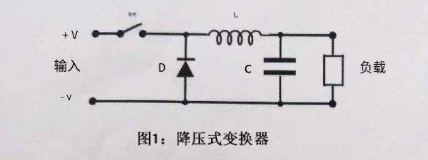
每年大约有8000~15000名心脏病患者将接受血液循环辅助器件的植入,如整体值入的人造心脏或与室腔有关的辅助器件[1]。一般来说,要激励心脏起博器需要6~20W功率,电能用透过皮层变压器线圈之间电感耦合方法透过皮层进行传输。该变压器次级部件被植入人体的皮下,初级部分放在人体的外面。变压器二个绕组间的间距约等于人类皮肤的厚度,通常在5~15mm之间[2],箝位型全桥串联谐振转换器用作该透过皮层进行能量传输系统的主要电路,图1示出了该系统的电路方块图。

图1 透过皮层电源系统的电路结构
由于线圈之间的间隔相对较大,这样会引起较大的漏感,因此,变压器中的损耗占了传输总能量中很大比率。在这种情况下,透过皮层的变压器设计对开发有效的透过皮层的电源系统尤为重要。
本文提出了一种透过皮层变压器的新型结构,它具有相对较高的传输效率,实验证明同换流器一起使用,它能透过皮层传输20W电能,效率达90%。关于人造心脏的电源系统用透过皮层变压器的研究工作已进行几年,这是我们大学人造心脏研究计划的组成部分。现已取得了以空气为媒介的实验结果,为了验证该变压器的性能,应进行体内测试。
二、能透过皮层的变压器的结构和材料
为得到很好的耦合,本文提出了一种新的线圈排列方式,如图2所示。初级铁心由MnZn基铁氧体罐形铁心(SIEMENS公司的P36×22 B65611-W-R30)机制而成,外径36mm,厚11mm,中部铁心直径16mm。次级铁心由厚度为0.035mm的柔性非晶磁带构成,然后把非晶带弯曲形成次级铁芯的外表面,这样可实现次级部分刚度较小。我们使用的非晶磁性材料FeNbCuMoCoBSI是一种具有低饱和磁致伸缩的铁基超微晶软磁合金,它除具有高的磁导率外,还具有若干其它优良的特性,例如在低的矫磁力下具有高的感应,在高频时反向磁化的损耗低。次级铁心的高度约7mm。由于铁氧体材料的铁心损耗在相同频率下低于非晶材料铁心的损耗,因此建议对具有较大电流的初级部分采用铁氧体材料。薄而轻的非晶带非常适于放入次级部分。初级线圈和次级线圈匝数分别为21匝和27匝,绕组线为40/38绞合线(相当于美国NH州新英格兰电线公司生产的22号线),外径约1mm,用此绞合线的目的在于减小高频时的趋肤效应。

图2 能透过皮层变压器的结构
三、特 性
为了将本文提出的透皮层变压器与传统的空气心透皮层变压器进行比较,我们研究分析了他们的磁通分布,这二种透皮层变压器的磁通密度图分别见图3和图4,他们是通过静磁有限单元模拟法得到的,我们从中可以看到用我们提出的结构能达到很好的互耦。

图3 空气心透皮层变压器磁通密度的模拟结果

图4 本文提出的透皮层变压器磁通密度的模拟结果
在我们的研究分析中,把电阻负载直接连接到没有整流器的次级绕组上,进行变压器和换流器传输效率的测量,图5示出了线圈之间间隙g与最大传输效率的关系曲线,线圈间障5mm,激励频率102.5kHz时的传输效率达90%。图6和图7分别示出了次级输出电压和传输功率的负载特性。图8示出了线圈之间间隙g与最大传输功率Ps的关系曲线。

图5 线圈之间间隙g与最大传输效率的关系曲线

图6 次级输出电压的负载特性

图7 传输功率的负载特性

图8 线圈之间间隙g与最大传输功率的关系曲线
我们研究了没有负载情况的输入和输出电压比与频率特性的函数关系,图9所示的测量结果表明在频率100 kHz~600kHz范围内电压比保持相对恒定,由于漏感相当大,故电压比不等于匝比。图10给出了本文推荐的透皮层变压器初、次级线圈电感与频率特性的实验结果,用HP4285A精密LCR表测得了频率范围75kHz~1kHz时的数值,由于材料磁导率随着频率的升高而降低,因此次级自感也随着频率的升高会降低。图11给出了在电流1mA时总损耗等效电阻与初、次级线圈频率特性函数曲线的实验结果,图中可看到随着频率的升高损耗明显磁大,尤其是次级线圈,这是由于铁心损耗的增大所致,因此建议本变压器的工作频率不高于200kHz。

图9 电压比与频率特性的关系曲线

图10 自感与频率特性的关系曲线

图11 自感与频率特性的关系曲线
四、结束语
本文提出了一种能透过皮层的变压器新型结构,它适用于人造心脏通过皮层传输能量的系统。其初级和次级铁心分别用铁氧体材料和非晶磁性材料制成,工作频率102.5kHz,线圈之间的间隙为5mm,它能透过皮层传输电能20W,最大传输效率达90%,本文同时讨论了本变压器的一些重要特性。
参考文献
[1]A. Ghahary and B.H. Cho, Design of a Transcutaneous Energy Transmission System Using a Series Resonant Converter,? IEEE PESC Rec., pp.1-8, 1990.
[2]Toshi Hiro Nishimura, et al., Characteristics of a novel energy transmission for a rechargeable cardiac pacemaker by using a resonant DC-DC converter,?IECON Proc., vol.2, pp. 875-880, 1993.
[3]H. Matsuki, et al., flexible transcutaneous transformer for artificial heart system,?IEEE Trans. Magn., vol. 26, No.5 pp. 1548-1559, 1990.
[4]H. Masuki, Energy transfer system utilizing amorphous wires for implantable medical devices,?IEEE Trans.Magn., vol.31, No.2, pp.1276-1282,1995.
[5]G.B.Joung, B.H.Cho, An energy transmission system for an artificial heart using leakage inductance compensation of transcutaneous transformer,?IEEE PESC Rec., vol. 1,pp.898-904,1996.
[6]Toshi Hiro Nishimura, et al., An advanced transcutaneous energy transformer for a rechargeable cardiac pacemaker battery by using a resonant DC to DC converter,?IECON Proc., vol.1,pp.524-529,1996.
[7]Toshi Hiro Nixhmura, et al., "A large air gap flat transformer for a transcutaneous energy transmission system,?IEEE PESC Rec., vol.2, pp.1323-1329,1994.
I INTRODUCTION
Every year an estimated 8,000 to 15,000 cardiac patients become potential candidates for implantation of circulatory assist devices such as totally implantable artificial heart of ventricular assist devices[1].In general,a power of 6~20W is required to drive the heart pump.Electrical energy can be transmitted transcutan-
eously by means of the inductive coupling between the coils of a transcutaneous transformer.The secondary part of the transformer would be implanted under the skin,and the primary would be placed outside the body.The distance between the transformer windings would be approximately equal to the thickness of the human skin,nominally between 5~15mm[2].A clamped-mode full-bridge series resonant converter is employed as the main circuit of the proposed transcutaneous energy transmission system.The block diagram of the system is shown in Fig.1.
Because of the large leakage inductance caused by relatively large gap between the coils,the loss in the transformer accounted for a high percentage of the transmitted total energy.In this case,the design of the transcutaneous transformer is significant in developing an efficient transcutaneous power supply system.
This paper presents a new structure transcutaneous transformer which has a relatively high transmission efficiency.The experimental results indicate that with the inverter it is possible to transmit an electrical energy of 20 watts transcutaneously with the efficiency up to 90%.Exploratory work on the use of the transcutaneous transformer in the power supply system for an artificial heart has so far been conducted.This forms part of a preliminary program to develop artificial heart in our university.The experimental results are obtained with air as the medium.In vivo testing should be carried out to verify the performance of the proposed transformer.
II STRUCTURE AND MATERIAL OF THE PROPOSED TRANSCUTANEOUS TRANSFORMER
Aiming to obtain a better coupling,a new arrangement of the coils as shown in Fig.2.is proposed.The primary core is machined from a MnZn-based ferrite pot core (SIEMENS,P36 22 B65611-W-R30),36mm in outer diameter,and 11mm thick,with the center core 16mm in diameter.The secondary core is made of flexible amorphous magnetic ribbons with the thickness of 0.035mm.The amorphous ribbons are subsequently bent to form the outer area of the secondary core.This enables the secondary part less rigid.FeNbCuMoCoBSI,the amorphous magnetic material in our use is a nanocrystalline soft magnetic alloy on a Fe base with low saturation magnetostriction.
Besides the high magnetic permeability,it also has some other good properties such as the high induction at low coercive force,the low losses on the reversal of magnetization at high frequencies.The height of the secondary core is around 7mm.Since the core loss of the ferrite material is less than that of the amorphous material under the same frequency,the ferrite material is recommended to be used at the primary part which has a higher current.The amorphous ribbon which is thin and light should be more suitable for implantation in the secondary part.The turns of primary and secondary coils are 21 and 27 respectively.The windings are 40/38 Litz wire(22 gauge equivalent,New England Electric Wire Corp.,Lisbon,NH,USA)with an outer diameter about 1mm.The use of Litz wire aims to reduce the skin effect in high frequency.
III CHARACTERISTICS
To compare the proposed transcutaneous transformer with the traditional air core transcutaneous transformer,their magnetic flux distribution has been studied.The magnetic flux density distribution maps of the two types of transcutaneous transformers are shown in Fig.3 and Fig.4 respectively.They are obtained through magnetostatic finite element simulation.It can be observed that a better mutual coupling can be achieved using the proposed structure.
In our study,resistive loads are connected directly to the secondary winding without rectifiers.The measurement of the transmission efficiency of the teansformer and inverter was carried out.Fig.5 shows the dependence of maximum transmission efficiency on gap between coils g.The transmission efficiency under the coil spacing 5mm and driving frequency 102.5kHz can be up to 90%.The load characteristics of the secondary output voltage and the transmitted power are shown in Fig 6 and Fig 7respectively Fig.8 shows the dependence of maximum transmitted power Ps on gap between coils g.
The input and output voltage ratio versus frequency characteristics for the no-load case is investigated.The measured results that are shown in Fig.9 indicate that the voltage ratio remains relatively constant in frequency range of 100k~600kHz.The voltage ratio is not equal to the winding ratio since leakage inductance is relatively high.
Fig.10 presents the experimental results for the inductance vs frequency characteristics of the primary and secondary coils of the proposed transcutaneous transformer.AHP4285A precision LCR meter was used to obtain the results over a frequency range of 75kHz to 1MHz.The secondary self-inductance decreased with increasing frequency due to the decreases in material permeability with increasing frequency.
Fig.11 presents the experimental results for the equivalent resistor of the total loss under the current level 1mA vs frequency characteristics of the primary and secondary coils.
It can be observed that the loss increases dramatically as the frequency increase especially in the secondary coil due to the increase of core loss.Therefore,the recommended operating frequency for this transformer is no more than 200kHz.
IV CONCLUSION
This paper presents a new structure transcutaneous transformer for an artificial heart transcutaneous energy transmission system.The primary and secondary cores are made of ferrite material and amorphous magnetic material respectively.With an operating frequency 102.5kHz and the distance between coils 5mm,it may transmit an electrical energy of 20 watts transcutaneously with the maximum transmission efficiency up to 90%.Some important characteristics of the proposed transformer are also shown and discussed in this paper.
A New Structure Transcutaneous Transformer for Artificial Heart System
提 要:本文介绍了一种新的适用于人造心脏系统的能透过皮层变压器的几何设 计,其初级铁心和次级铁心分别由铁氧体和非晶材料制成。实验证明它 可传递电功率20W,足以激励心脏起博器。线圈之间的间隙为20mm,同换 流器一起它的传输效率达90%,开关频率102.5kHz。本文对该变压器的某 些特性提出了讨论。
主题词:透过皮层的变压器 人造心脏系统 传输效率 磁通分布
Abstract:A new geometrical design of transcutaneous transformer for artificial heart system is presented in this paper.The primary and secondary cores are made of ferrite and amorphous magnetic materials respectively.The experimental results indicate that it is possible to transmit an electrical power of 20W which is sufficient to drive the heart pump.With a gap of 5mm between the coils,its transmission efficiency with the inverter can be up to 90% with a switching frequency 102.5kHz.Some characteristics of the proposed transformer are also shown and discussed in this paper.
Index Terms:Transcutaneous transformer,artificial heart system ,transmission efficiency,flux distribution.
一、引 言
每年大约有8000~15000名心脏病患者将接受血液循环辅助器件的植入,如整体值入的人造心脏或与室腔有关的辅助器件[1]。一般来说,要激励心脏起博器需要6~20W功率,电能用透过皮层变压器线圈之间电感耦合方法透过皮层进行传输。该变压器次级部件被植入人体的皮下,初级部分放在人体的外面。变压器二个绕组间的间距约等于人类皮肤的厚度,通常在5~15mm之间[2],箝位型全桥串联谐振转换器用作该透过皮层进行能量传输系统的主要电路,图1示出了该系统的电路方块图。
图1 透过皮层电源系统的电路结构
由于线圈之间的间隔相对较大,这样会引起较大的漏感,因此,变压器中的损耗占了传输总能量中很大比率。在这种情况下,透过皮层的变压器设计对开发有效的透过皮层的电源系统尤为重要。
本文提出了一种透过皮层变压器的新型结构,它具有相对较高的传输效率,实验证明同换流器一起使用,它能透过皮层传输20W电能,效率达90%。关于人造心脏的电源系统用透过皮层变压器的研究工作已进行几年,这是我们大学人造心脏研究计划的组成部分。现已取得了以空气为媒介的实验结果,为了验证该变压器的性能,应进行体内测试。
二、能透过皮层的变压器的结构和材料
为得到很好的耦合,本文提出了一种新的线圈排列方式,如图2所示。初级铁心由MnZn基铁氧体罐形铁心(SIEMENS公司的P36×22 B65611-W-R30)机制而成,外径36mm,厚11mm,中部铁心直径16mm。次级铁心由厚度为0.035mm的柔性非晶磁带构成,然后把非晶带弯曲形成次级铁芯的外表面,这样可实现次级部分刚度较小。我们使用的非晶磁性材料FeNbCuMoCoBSI是一种具有低饱和磁致伸缩的铁基超微晶软磁合金,它除具有高的磁导率外,还具有若干其它优良的特性,例如在低的矫磁力下具有高的感应,在高频时反向磁化的损耗低。次级铁心的高度约7mm。由于铁氧体材料的铁心损耗在相同频率下低于非晶材料铁心的损耗,因此建议对具有较大电流的初级部分采用铁氧体材料。薄而轻的非晶带非常适于放入次级部分。初级线圈和次级线圈匝数分别为21匝和27匝,绕组线为40/38绞合线(相当于美国NH州新英格兰电线公司生产的22号线),外径约1mm,用此绞合线的目的在于减小高频时的趋肤效应。
图2 能透过皮层变压器的结构
三、特 性
为了将本文提出的透皮层变压器与传统的空气心透皮层变压器进行比较,我们研究分析了他们的磁通分布,这二种透皮层变压器的磁通密度图分别见图3和图4,他们是通过静磁有限单元模拟法得到的,我们从中可以看到用我们提出的结构能达到很好的互耦。
图3 空气心透皮层变压器磁通密度的模拟结果
图4 本文提出的透皮层变压器磁通密度的模拟结果
在我们的研究分析中,把电阻负载直接连接到没有整流器的次级绕组上,进行变压器和换流器传输效率的测量,图5示出了线圈之间间隙g与最大传输效率的关系曲线,线圈间障5mm,激励频率102.5kHz时的传输效率达90%。图6和图7分别示出了次级输出电压和传输功率的负载特性。图8示出了线圈之间间隙g与最大传输功率Ps的关系曲线。
图5 线圈之间间隙g与最大传输效率的关系曲线
图6 次级输出电压的负载特性
图7 传输功率的负载特性
图8 线圈之间间隙g与最大传输功率的关系曲线
我们研究了没有负载情况的输入和输出电压比与频率特性的函数关系,图9所示的测量结果表明在频率100 kHz~600kHz范围内电压比保持相对恒定,由于漏感相当大,故电压比不等于匝比。图10给出了本文推荐的透皮层变压器初、次级线圈电感与频率特性的实验结果,用HP4285A精密LCR表测得了频率范围75kHz~1kHz时的数值,由于材料磁导率随着频率的升高而降低,因此次级自感也随着频率的升高会降低。图11给出了在电流1mA时总损耗等效电阻与初、次级线圈频率特性函数曲线的实验结果,图中可看到随着频率的升高损耗明显磁大,尤其是次级线圈,这是由于铁心损耗的增大所致,因此建议本变压器的工作频率不高于200kHz。
图9 电压比与频率特性的关系曲线
图10 自感与频率特性的关系曲线
图11 自感与频率特性的关系曲线
四、结束语
本文提出了一种能透过皮层的变压器新型结构,它适用于人造心脏通过皮层传输能量的系统。其初级和次级铁心分别用铁氧体材料和非晶磁性材料制成,工作频率102.5kHz,线圈之间的间隙为5mm,它能透过皮层传输电能20W,最大传输效率达90%,本文同时讨论了本变压器的一些重要特性。
参考文献
[1]A. Ghahary and B.H. Cho, Design of a Transcutaneous Energy Transmission System Using a Series Resonant Converter,? IEEE PESC Rec., pp.1-8, 1990.
[2]Toshi Hiro Nishimura, et al., Characteristics of a novel energy transmission for a rechargeable cardiac pacemaker by using a resonant DC-DC converter,?IECON Proc., vol.2, pp. 875-880, 1993.
[3]H. Matsuki, et al., flexible transcutaneous transformer for artificial heart system,?IEEE Trans. Magn., vol. 26, No.5 pp. 1548-1559, 1990.
[4]H. Masuki, Energy transfer system utilizing amorphous wires for implantable medical devices,?IEEE Trans.Magn., vol.31, No.2, pp.1276-1282,1995.
[5]G.B.Joung, B.H.Cho, An energy transmission system for an artificial heart using leakage inductance compensation of transcutaneous transformer,?IEEE PESC Rec., vol. 1,pp.898-904,1996.
[6]Toshi Hiro Nishimura, et al., An advanced transcutaneous energy transformer for a rechargeable cardiac pacemaker battery by using a resonant DC to DC converter,?IECON Proc., vol.1,pp.524-529,1996.
[7]Toshi Hiro Nixhmura, et al., "A large air gap flat transformer for a transcutaneous energy transmission system,?IEEE PESC Rec., vol.2, pp.1323-1329,1994.
I INTRODUCTION
Every year an estimated 8,000 to 15,000 cardiac patients become potential candidates for implantation of circulatory assist devices such as totally implantable artificial heart of ventricular assist devices[1].In general,a power of 6~20W is required to drive the heart pump.Electrical energy can be transmitted transcutan-
eously by means of the inductive coupling between the coils of a transcutaneous transformer.The secondary part of the transformer would be implanted under the skin,and the primary would be placed outside the body.The distance between the transformer windings would be approximately equal to the thickness of the human skin,nominally between 5~15mm[2].A clamped-mode full-bridge series resonant converter is employed as the main circuit of the proposed transcutaneous energy transmission system.The block diagram of the system is shown in Fig.1.
Because of the large leakage inductance caused by relatively large gap between the coils,the loss in the transformer accounted for a high percentage of the transmitted total energy.In this case,the design of the transcutaneous transformer is significant in developing an efficient transcutaneous power supply system.
This paper presents a new structure transcutaneous transformer which has a relatively high transmission efficiency.The experimental results indicate that with the inverter it is possible to transmit an electrical energy of 20 watts transcutaneously with the efficiency up to 90%.Exploratory work on the use of the transcutaneous transformer in the power supply system for an artificial heart has so far been conducted.This forms part of a preliminary program to develop artificial heart in our university.The experimental results are obtained with air as the medium.In vivo testing should be carried out to verify the performance of the proposed transformer.
II STRUCTURE AND MATERIAL OF THE PROPOSED TRANSCUTANEOUS TRANSFORMER
Aiming to obtain a better coupling,a new arrangement of the coils as shown in Fig.2.is proposed.The primary core is machined from a MnZn-based ferrite pot core (SIEMENS,P36 22 B65611-W-R30),36mm in outer diameter,and 11mm thick,with the center core 16mm in diameter.The secondary core is made of flexible amorphous magnetic ribbons with the thickness of 0.035mm.The amorphous ribbons are subsequently bent to form the outer area of the secondary core.This enables the secondary part less rigid.FeNbCuMoCoBSI,the amorphous magnetic material in our use is a nanocrystalline soft magnetic alloy on a Fe base with low saturation magnetostriction.
Besides the high magnetic permeability,it also has some other good properties such as the high induction at low coercive force,the low losses on the reversal of magnetization at high frequencies.The height of the secondary core is around 7mm.Since the core loss of the ferrite material is less than that of the amorphous material under the same frequency,the ferrite material is recommended to be used at the primary part which has a higher current.The amorphous ribbon which is thin and light should be more suitable for implantation in the secondary part.The turns of primary and secondary coils are 21 and 27 respectively.The windings are 40/38 Litz wire(22 gauge equivalent,New England Electric Wire Corp.,Lisbon,NH,USA)with an outer diameter about 1mm.The use of Litz wire aims to reduce the skin effect in high frequency.
III CHARACTERISTICS
To compare the proposed transcutaneous transformer with the traditional air core transcutaneous transformer,their magnetic flux distribution has been studied.The magnetic flux density distribution maps of the two types of transcutaneous transformers are shown in Fig.3 and Fig.4 respectively.They are obtained through magnetostatic finite element simulation.It can be observed that a better mutual coupling can be achieved using the proposed structure.
In our study,resistive loads are connected directly to the secondary winding without rectifiers.The measurement of the transmission efficiency of the teansformer and inverter was carried out.Fig.5 shows the dependence of maximum transmission efficiency on gap between coils g.The transmission efficiency under the coil spacing 5mm and driving frequency 102.5kHz can be up to 90%.The load characteristics of the secondary output voltage and the transmitted power are shown in Fig 6 and Fig 7respectively Fig.8 shows the dependence of maximum transmitted power Ps on gap between coils g.
The input and output voltage ratio versus frequency characteristics for the no-load case is investigated.The measured results that are shown in Fig.9 indicate that the voltage ratio remains relatively constant in frequency range of 100k~600kHz.The voltage ratio is not equal to the winding ratio since leakage inductance is relatively high.
Fig.10 presents the experimental results for the inductance vs frequency characteristics of the primary and secondary coils of the proposed transcutaneous transformer.AHP4285A precision LCR meter was used to obtain the results over a frequency range of 75kHz to 1MHz.The secondary self-inductance decreased with increasing frequency due to the decreases in material permeability with increasing frequency.
Fig.11 presents the experimental results for the equivalent resistor of the total loss under the current level 1mA vs frequency characteristics of the primary and secondary coils.
It can be observed that the loss increases dramatically as the frequency increase especially in the secondary coil due to the increase of core loss.Therefore,the recommended operating frequency for this transformer is no more than 200kHz.
IV CONCLUSION
This paper presents a new structure transcutaneous transformer for an artificial heart transcutaneous energy transmission system.The primary and secondary cores are made of ferrite material and amorphous magnetic material respectively.With an operating frequency 102.5kHz and the distance between coils 5mm,it may transmit an electrical energy of 20 watts transcutaneously with the maximum transmission efficiency up to 90%.Some important characteristics of the proposed transformer are also shown and discussed in this paper.


暂无评论